To ensure safe installation of Double Wall Underground Fuel Storage Tanks, it is important for installer to make sure all steps of installation is done correctly and follow certain guideline. Without proper installation, underground tank might be subjected to direct physical damage or compromise its quality.
Understand Double Wall – FRP Jacketed Steel Tank
Double Wall – FRP Jacketed Steel Tank provide a form of secondary containment in that it contains an internal cavity (that is the space between the inner steel and outer fibre walls) which called an interstice. This space may also be referred to as an interstitial space, an annulus or an annular space.
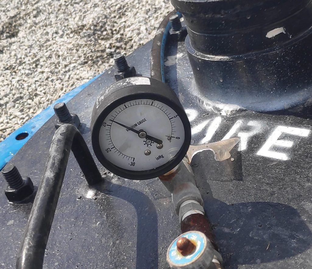
In common practice, these tanks are shipped from the factory with a minimum of 15 inches Hg vacuum inside the tank interstice. A vacuum gauge is factory-installed on the tank to monitor the interstice vacuum pressure.
More info click here
Installation Guide
1st Step: Excavation
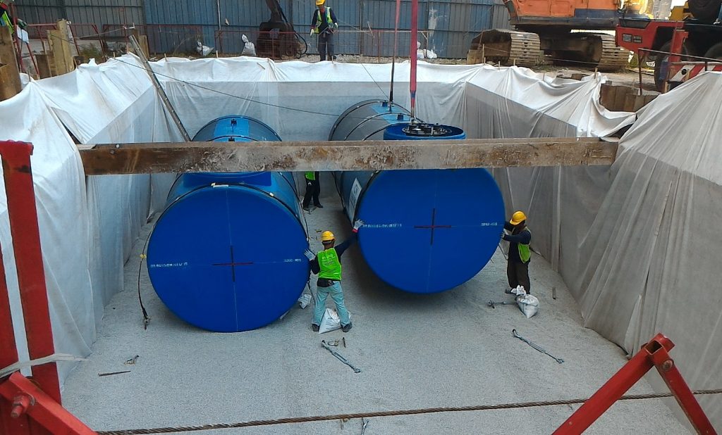
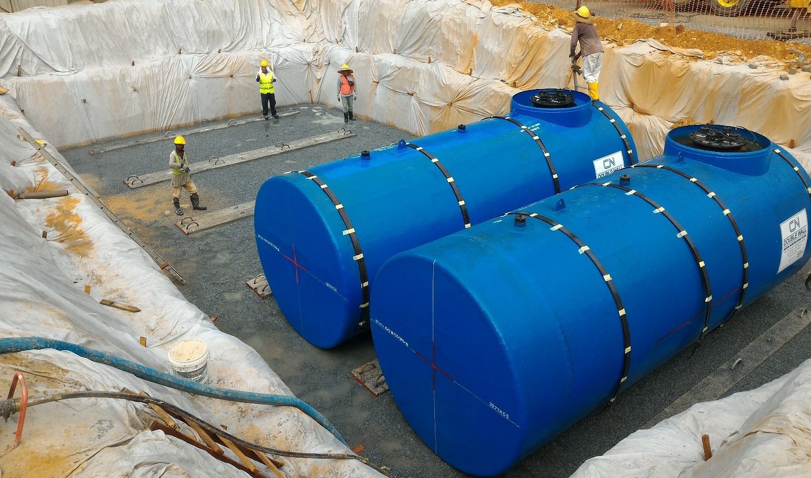
Remove all loose soil. Level and compact the bottom of excavation pit. Use backfill material (not soil) to fill low areas in excavation. If geotextile fabric is to be used, it should normally be placed in the pit at this time. Excavation for tanks should be large enough to provide a minimum clearance of 24 inches between the ends and sides of tanks and sides of the excavation. Tanks should be at least 24 inches apart. Recommended minimum bury depth of 1.2 meters (4ft) and maximum bury depth of 2.1 meters (7ft) is optimal to account for pipe slope requirements and adequate tank overburden. The excavation should be free from any hard or sharp material that may cause damage to the tank.
Where soil is soft, loose or likely to crack and crumble after the excavation, the clearances around the sides and ends of the tank will be affected by the backslope requirements of the excavation. In such conditions, the sidewalls must be backsloped to allow a minimum of ½ tank diameter from the end and sides of tank to the excavation walls. All loose materials must be removed from the excavation prior to bedding.
For a tidal area or wet excavation pit, install appropriate dewatering and pumping equipment. A shallow pump-out well, filled with backfill material, maybe installed at the corners of the excavation. Maintain water level as low as possible at all times.

Pit Excavation Size
2nd Step: Bedding
The bottom of the excavation should be covered with a minimum of 12 inches of bedding, suitably graded and levelled.
If anchoring is by means of a concrete pad, the tank should not be placed directly on the pad. Bedding material 6-12 inches deep must be spread evenly over the dimensions of the pad to separate the tank from the pad. Paving of the pad must extend at least 24 inches beyond all points of the tanks.
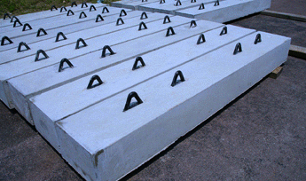
If dead man anchors are used, a layer of backfill material 4 inches deep should be installed to properly bed the dead man anchor beams. The dead man anchors are laid on the 4 inches bedding, and subsequently bedding material 12 inches deep is spread evenly between the anchors and all over the pit bottom.
Bedding and backfill material should consist of homogeneous pea gravel, crushed stone, clean sand or natural earthen material. Crushed stone, clean sand and natural earthen materials shall be capable of passing 100% through a 1/2 inch (13mm) sieve and not more than 12% by dry weight through a # 200 sieve (0.0029 inch/0.0754 mm). Pea gravel should be no larger than 3/4 inch (19mm). The materials should be free of all foreign materials such as native soil, bricks, metal, concrete and plastic.
In a tidal area, the tank bedding material shall be pea gravel or crushed stone. Sand and natural earthen material may be used only if measures are taken to prevent washout of materials during the design life of the system. Irrespective, however, sand bedding/backfill material must not be used for FRP Jacketed Steel Tanks.
3rd Step: Concrete Slab or Deadman Anchor
Concrete Slab
Concrete slabs should be 24 inches wider and longer than the tank. Rebar should be placed 3 inches from the top of the concrete slab and 3 inches from the bottom of the slab. Two additional #6 rebar should be placed both top and bottom running the length of the concrete slab by each row of anchor bolts to distribute the anchor bolt loads.

Concrete Slab
Deadman Anchor
Deadman anchor beams are laid on top of a pre-prepared 4 inches bedding, parallel to the pit wall and to each other, properly spaced, aligned and levelled. An additional layer of bedding material 12 inches deep must be spread evenly between the anchors and over the pit bottom, graded, compacted and levelled. Ensure there is no anchor movement if bedding is compacted.

Deadman Anchor
4th Step: Inspection
Inspect each tank whilst on the trailer for visual signs of damage to the body and fittings, paying particular attention to presence of serious abrasions along the sides and bottom of tank possibly caused by contact with the trailer bed or sides. Check vacuum gauge reading to make sure no drop of pressure, and also verify all accessories required.
To prevent damage to the fibre jacket and structure, the tank should be handled with care during, handling, storage and installation. Tank should not be rolled, dragged, rubbed against each other or other surfaces or handled with equipment or devices that might impose damage or excessive stress. Care should also be taken to prevent impact of the tank with any hard object which can damage the tank, such as, concrete pad, other tanks or compaction equipment. The tank should be slowly and carefully lifted and lowered into the excavation without jerking, dragging or dropping, by use of cables, chains or web slings of adequate length attached to the lifting lugs. Chains, cables, web slings etc. should not be placed around the tank to lift or move it (however, rope or strapping that will not damage the coating may be used to secure the tank during transit).
The angle between the horizontal and one side of the lifting cable must not be less than 60 degrees. Prior to moving the tank, a determination should be made that the hoisting equipment has sufficient capacity and reach to lift and lower the tank without dropping or dragging.
5th Step: Tank Placing
Place tank centrally onto prepared bed between the two dead man anchors, or in between the anchor bolts of the concrete pad. Ensure tanks are aligned, level and not rotated, and properly spaced for placement of straps. Spirit level can be used against datum lines to check levelness of tanks.
6th Step: Anchoring
High water tables or partially flooded excavation sites exert significant upward buoyant forces on tanks. Buoyant forces are partially resisted by the weight of the tank, depth of excavation, the backfill and the pavement on top of the tank. Additional buoyant restraints, when required, are obtained using properly designed hold-down straps in conjunction with concrete hold-down pads or dead man anchor beams. The tanks are provided with a hold-down strap system consisting of flat steel bars, rubber pads for isolation of metal straps from tank, shackles and turnbuckles for connection and adjustment.
After the tank is placed onto the prepared bed, place straps over the tank, align appropriately, and connect one end to shackle fitted to the hold-down bolt on dead man anchor. Connect the other end to a turnbuckle fitted to the hold down bolt of the dead man anchor on the other side of the tank. Adjust turnbuckles till strap is snug but do not over-tighten. Repeat procedure for each hold-down position along the tank.
7th Step: Backfilling
Suitable backfill material similar to bedding material should be used. Pea gravel or crushed stone is recommended for FRP jacketed tank. After the tank is strapped down, proceed to backfill the installed tanks from the 5 o clock to 7 o clock tank positions. Sufficient backfill material shall be placed carefully around the entire tank bottom and consolidated along the bottom and under the tank shell. Use a wooden tamping rod to manually push backfill under the tank and tamp until all voids are filled and solid resistance is felt.
Once backfill has reached at least 24 inches around the sides of the tank and compaction beneath the tanks has been spot checked to ensure there are no voids, proceed to backfill other areas evenly up to the level of backfill surrounding the bottom quadrant of the tank. Compact if necessary.

Vacuum Gauge.
Check vacuum gauge reading after backfilling. Reading should be remained same for 24 hours.
For further enquiry, feel free to approach our technical team HERE.


